Remote Controlled Submarine
Objective Summary
Build a remote controlled submarine that can explore neat underwater environments.

Further Background
At the end of high school, I needed a summer project that I could work on for fun. This is what I ended up choosing!
Note: this project ended up being ten times more challenging than I originally anticipated. I ran into a plethora of problems, some of which I am still working on resolving to this day (3 years later).
Process
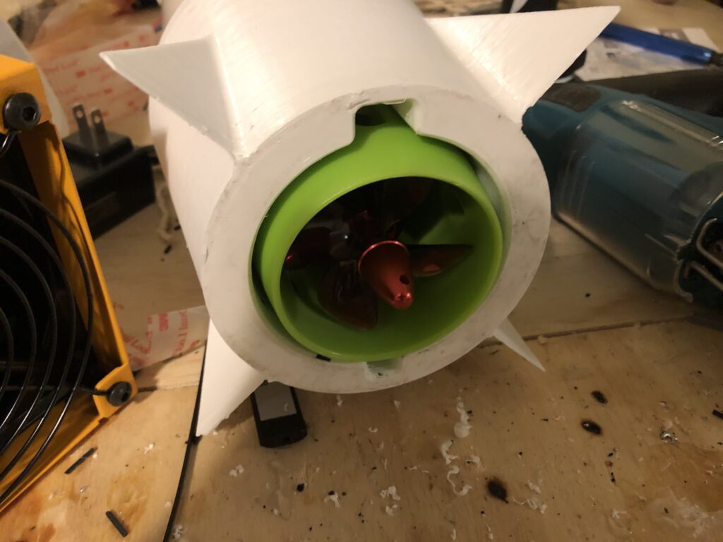
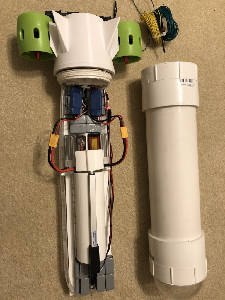
The submarine operates on a differential steering system; using two hobby-grade brushless DC motors controlled by two electronic speed controllers wired up to an RC receiver. The system runs off of two 3S LiPo batteries. The image to the right shows my attempt to use a single brushless motor with a servo-controlled rudder, however that was unsuccessful. Images below show two separate motors on either side of the plastic rear.

I use a custom ballast system for depth control. Inside of the submarine lies a large syringe, and it is attached to a linear actuator that is connected to the RC receiver. The syringe pumps water in and out of the submarine to control its density; the submarine’s mass is calibrated so that when the syringe is full of water, its density is >1 so that it sinks, and when the syringe is expelled, its density is <1 so that the sub floats. Note: the video to the right shows an earlier version that uses two 100mL syringes. This was later replaced with a single 0.5L syringe.
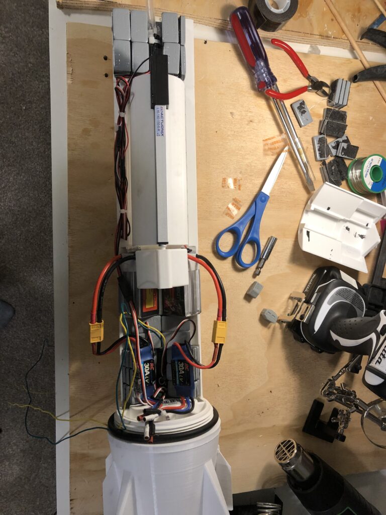
All the internal systems fit within a long 3D printed internal assembly that easily slides into the submarine housing. I like to call this assembly the “guts” of the submarine.
From the top to the bottom of this internal assembly:
- Ballasting weights.
- An endoscope camera and some RC-controlled lights get a live feed of what the submarine is seeing underwater.
- The linear actuator/syringe ballast system.
- The two 3S LiPo batteries.
- The two ESCs and some more ballasting weights.
- The old version of the 3D printed end cap of the submarine. It was sealed with a large O-ring gasket, which I later discovered was insufficient.


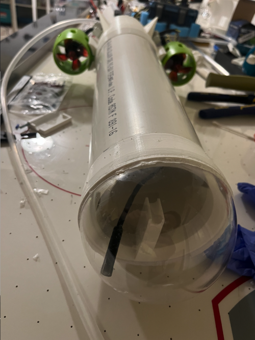
This entire internal assembly slides into the “sheath” housing of the submarine, which is primarily made of a large diameter PVC pipe that is capped by some 3D printed parts. At one end, there is a clear half of a plastic Christmas ornament dome that serves as a viewing window for the endoscope camera. At the other end, there is the opening to slide in the internal assembly.
The image to the left is an older version of the submarine. However, in my newer version (not pictured), the rear opening is capped by a screwable watertight PVC pipe plug when ready for use. This pipe plug solution took me probably 6 months to arrive at; everything else would leak some amount of water into the hull. And you know what happens when water and electronics mix.
Progress (as of Dec 2023)
The submarine does in fact look somewhat like a submarine. To my chagrin, my non-engineering friends also tell me that it looks like a ballistic missile.
The last time I tested my submarine in a body of water (the Stanford public swimming pool), the submarine turned into a torpedo and ran into several small children. I was subsequently kicked out of the pool by the lifeguard. I will post a video of the submarine working here once I figure out how to avoid this undesired outcome.
Continued Challenges
- The submarine goes way too fast. I will either modify settings on the RC transmitter to slow down the motors, or I can add resistors in series with the motor. I may also attempt to do a fancier solution and mess with PWM.
- The submarine’s turning radius is massive. It also does not go backwards. To reduce the turning radius, I might attempt to reintroduce a rudder.
- The plastic dome on the front of the submarine is very brittle and will certainly shatter upon the submarine impacting something at high speed. Thus, I will replace the dome with something sturdier before this happens.
- I know that RC signals do not penetrate water at all. My previous naive solution was to keep the RC transmitter inside the submarine hull and splice in some long wire before the antenna so that the antenna would float above the surface on a buoy. Unfortunately, this does not work, as the entire receiver, not just the antennas, have to be above the surface of the water to ensure a stable connection. However, a large amount of different wires (from the DC motors, linear actuator, lights, etc) all have to connect to the receiver. Thus, I will need to keep the entire receiver above water in the buoy and have a 12-cable tether running from the submarine, through the open water, and into the receiver. Unfortunately, 12-wire shielded cable is incredibly expensive.