Polar Rover
Objective Summary
Build a GPS-navigated, autonomous, solar-powered rover to navigate from the Antarctic coast to the South Pole and back.
Further Background
Stanford Space Initiative is the largest engineering club at Stanford with hundreds of members. The club is split into seven subteams. I am co-lead of the Mars team, which is focused on Mars-based technologies and projects. We anticipate that in the near future, NASA will aim to explore the surface of the Martian polar ice caps. Thus, I am leading a project to construct a rover that will use Antarctica’s terrain as an analog for this Martian environment. I run the team of 20 active engineering students, and I operate my team’s annual budget of $15,000.
See our Wiki: https://ssi-wiki.stanford.edu/Category:Mars
Design Considerations
- Ground resupply vehicles have to consistently travel from McMurdo Station at the Antarctic coast to the Amundsen-Scott Station at the South Pole. They follow a well-charted path called the Antarctic Overland Traverse. Our rover will use GPS waypoint navigation to follow that exact path.
- Solar power is the only consistent, long-term energy source available to us in Antarctica. However, the sun only consistently shines during the Antarctic summer, which lasts from October-February. Thus, that is our window to depart and return from our journey.
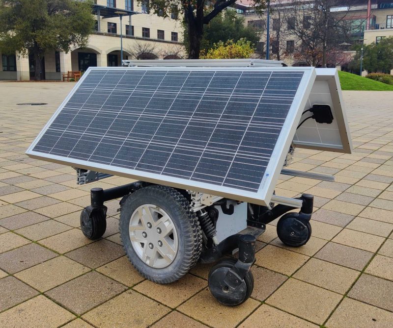
- The sun stays relatively low to the horizon during the entirety of the summer. Thus, we need to mount the solar panels nearly perpendicular to the ground. This is not shown in the current prototype rover, which is only meant to operate in California.
- We need internet to livestream video from the rover back to us at Stanford. Thus, we use a Starlink satellite internet atop the rover.
- The rover will be primarily autonomous. We will use GPS for a long-range pre-planned route and LiDAR short-range path planning and object avoidance. However, we anticipate that things can and will still go wrong (i.e. the rover will divert from its path, might get stuck in the snow, etc). Thus, we will route Starlink internet into a Jetson Nano in order to SSH in and take manual remote control of the rover (from back at Stanford) whenever necessary.

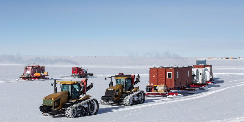
Map of the Antarctic Overland Traverse
Visual of the Antarctic Overland Traverse
Process
We first built a small, prototype rover to test essential capabilities. This rover was built atop an off-the-shelf hobby-grade RC vehicle kit. We heavily modified it to include GPS waypoint navigation, thermal insulation, and rudimentary sensor data (temperature, velocity, and heading). Furthermore, we toyed with adding a 2D LiDAR module to add rudimentary path-planning, but we then decided to save this step for work on a later version of the rover. This prototype rover is several orders of magnitude smaller than the more recent iteration of the rover we built later on (see below), which is to include a more complete suite of capabilities.

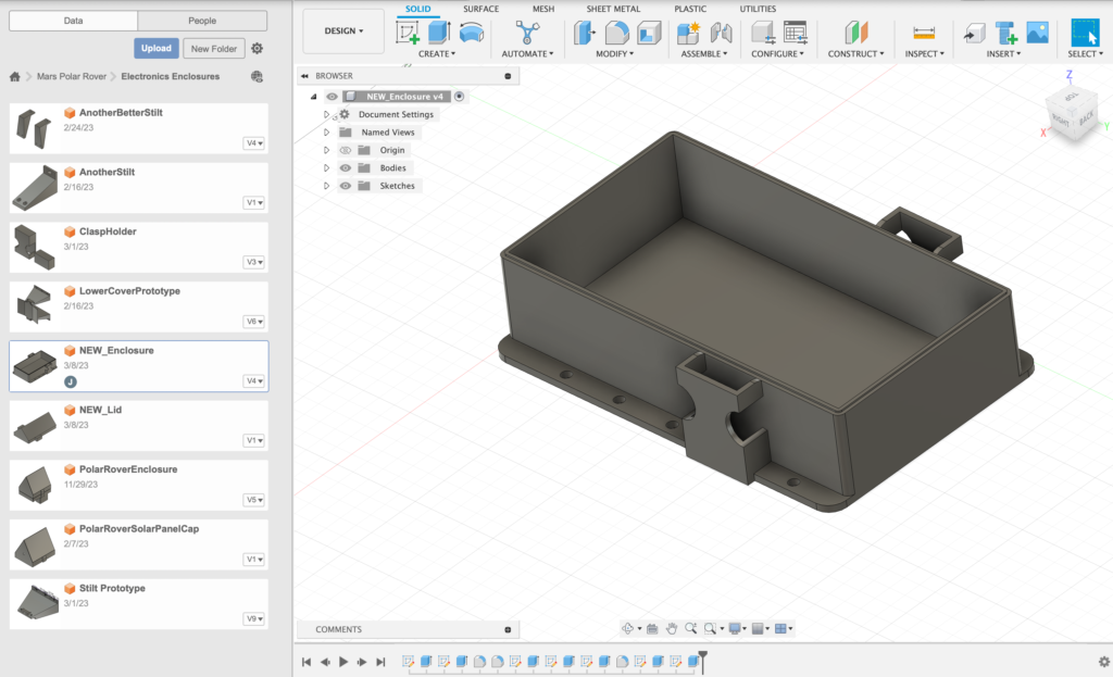
Seen here: I designed and 3D printed a waterproof enclosure for the prototype rover’s essential electronics. This enclosure has easily removable latches and an A-frame roof to mount small solar panels and to prevent rainfall accumulation on the roof. We padded the interior of the enclosure with thermally insulating padding and a rubber gasket for a watertight seal. The LiPo battery, ESC, RC receiver, internet module, and more fit within this enclosure.
Seen here: we are testing the rover’s navigation with a figure 8 path that was programmed into the Ardupilot mission planner software at a retreat at a team member’s house in Portola Valley. We physically drew out a figure 8 pattern on the map within APM, and the rover followed that path using its GPS module. Pardon the sideways wheelie!
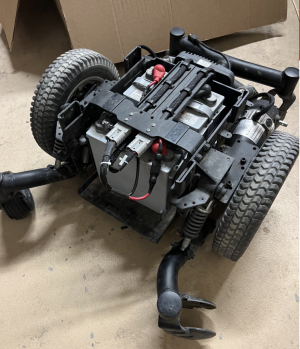
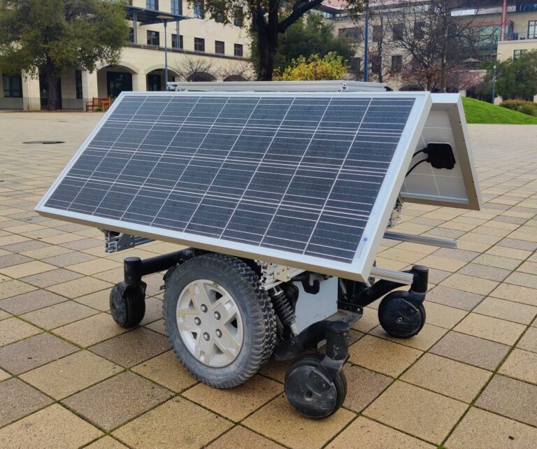
We continued on to the next phase of the project: construction of a 1:1 scale rover. The chassis was built atop a heavy-duty electric wheelchair frame with all unnecessary components removed. We received help from Cislune, a small aerospace startup, for help with this stage. The wheelchair base runs on two 12V lead-acid batteries. It is 2WD (the main tires in the center) with suspension and has four passive casters at the corners. We soon aim to replace the casters with a more snow-capable option. We even considered modifying the drivetrain into a tracked/treaded system, however I anticipate that will be quite the challenge.
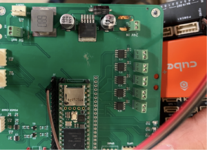
Seen here: a Cislune custom PCB with an integrated Teensy microcontroller that enables external interfacing with the rover’s control systems. We wired this PCB to a Pixhawk module to allow for control via autopilot software. We had to troubleshoot a significant amount of software issues with the Teensy before we managed to get it working. We first had success with teleoperated control (directly driving the rover via an RC transmitter).
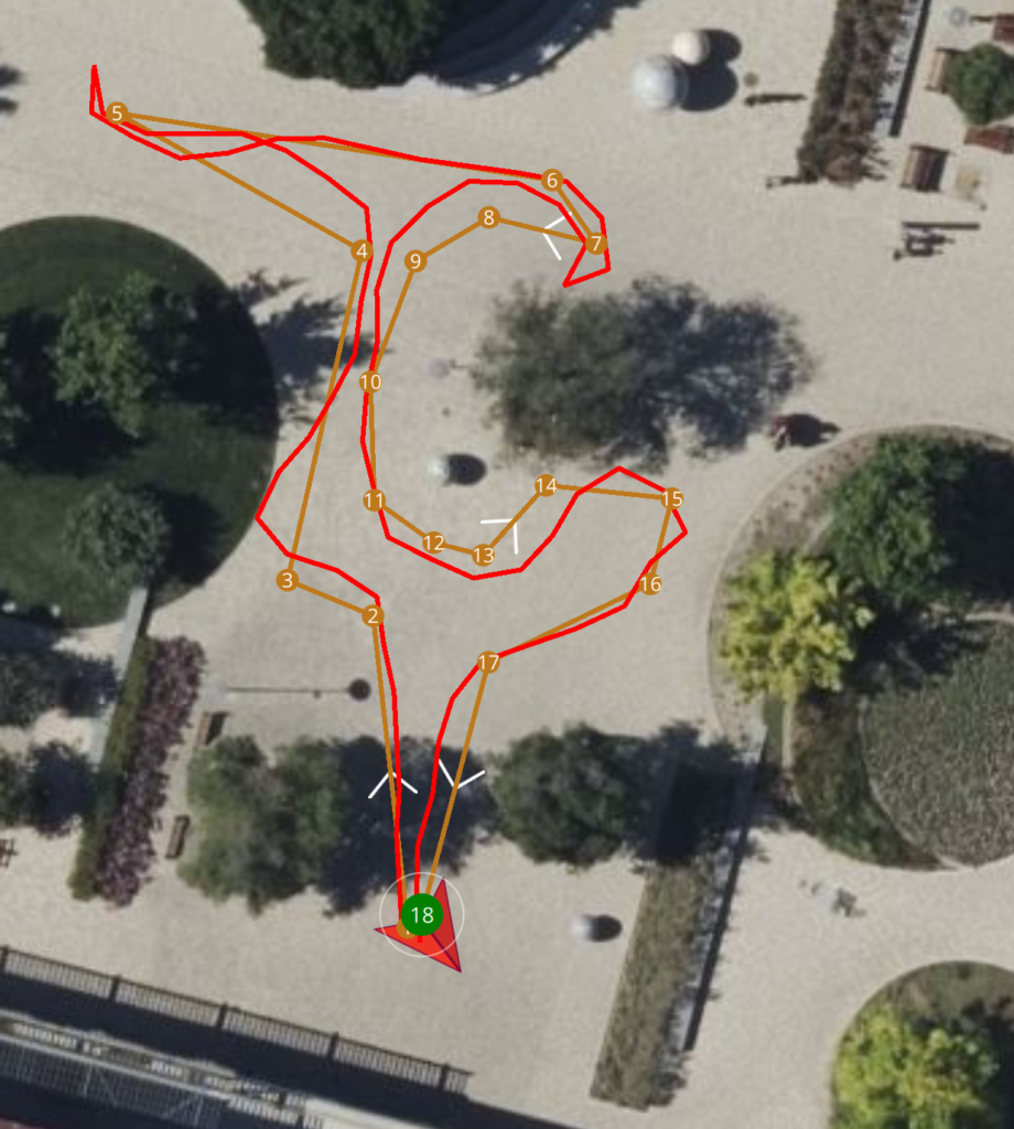
Seen here: we next enabled GPS waypoint navigation on the larger rover. We are driving the rover around Stanford’s engineering quad at night purely by clicking points on a map. Yellow marks the planned path, and red marks the actual path traveled.
Seen here: we recently installed two 200W solar panels on the sides of the rover using aluminum extrusion and brackets for mounting. We also integrated a solar charge controller module to scrape crucial specs from the power system, including battery voltage, charging rate, etc. Now, the rover is fully rechargeable and power-independent. The panels seen to the right are mounted at approximately a 45 degree angle for use in California. However, when the rover is taken to Antarctica, we will adjust this angle to be nearly perpendicular to the ground to account for the sun’s position close to the horizon when near the poles.
Next Steps (as of Dec 2023)
Progress has been steady, but there is still much work to be done on the rover. Immediate next steps include:
- Integrating the Starlink module for internet live streaming.
- Interfacing the rover’s PCB and Pixhawk autopilot module with a Jetson Nano.
- Integrating LiDAR onto the rover for basic object avoidance and path planning.